Archived Project

This is an old project, and probably no one currently at Omega Verksted knows anything more about it than what is provided on this page. You can try to recreate it if you want, but the documentation is provided as-is and it may be outdated.

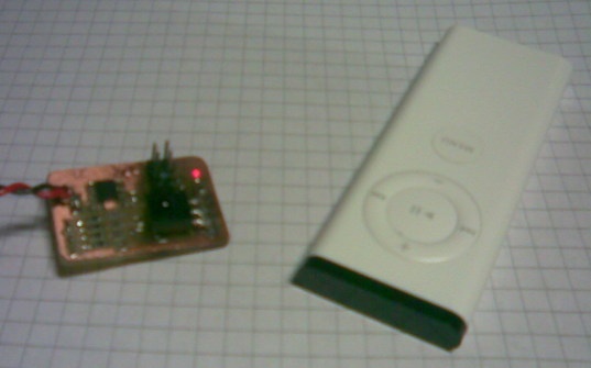
IrCom is a project aimed at creating an IR interface to use with a remote control. The main motivation for this project was to be able to control the robot in RoboCom with the nifty little apple universal remote. This involved a considerable amount of backwards-engineering, (or "hacking" if you wish), since the protocol used in the remote has not been officially published.

Reverse engineering the protocol

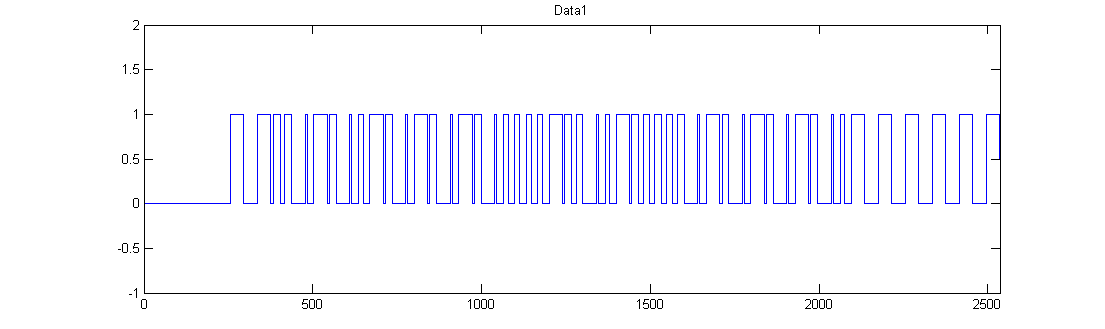
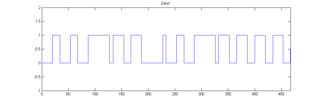
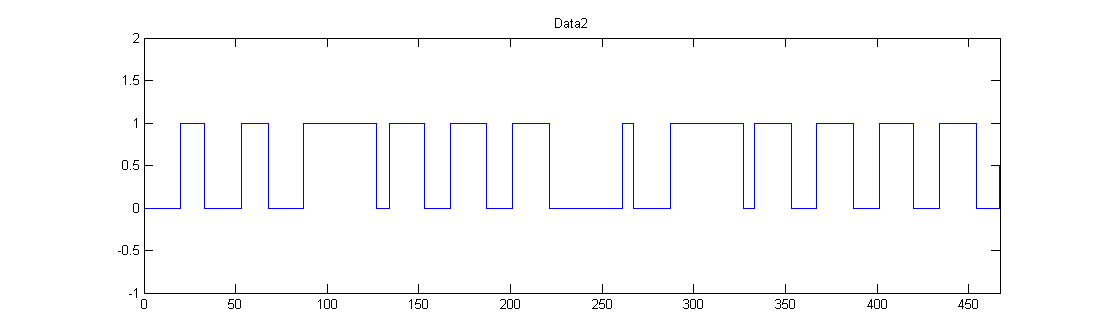
The first step was to find out what exactly the little remote control sends when you push a button. This was not quite easy, since the protocol appeared to be quite complex. Work had previosly been done on a Sony remote protocol, which is really simple in comparison. A sensor was attached to an AVR, which had an CP2103 USB to UART connected to it. Thus information received from the IR sensor could be sent to a computer. A test program was written for the AVR, for measuring the time between rising and falling flanks of the input from the sensor. This information was then sent to a computer, where some processing in MATLAB yielded some interresting results.

By comparing the subtle differences in a certain part of the signals, a general idea could be formed about how to write a program for identifying which button is pressed.

Signal sniffs

Receiver with remote


Portion of a signal from the IR sensor

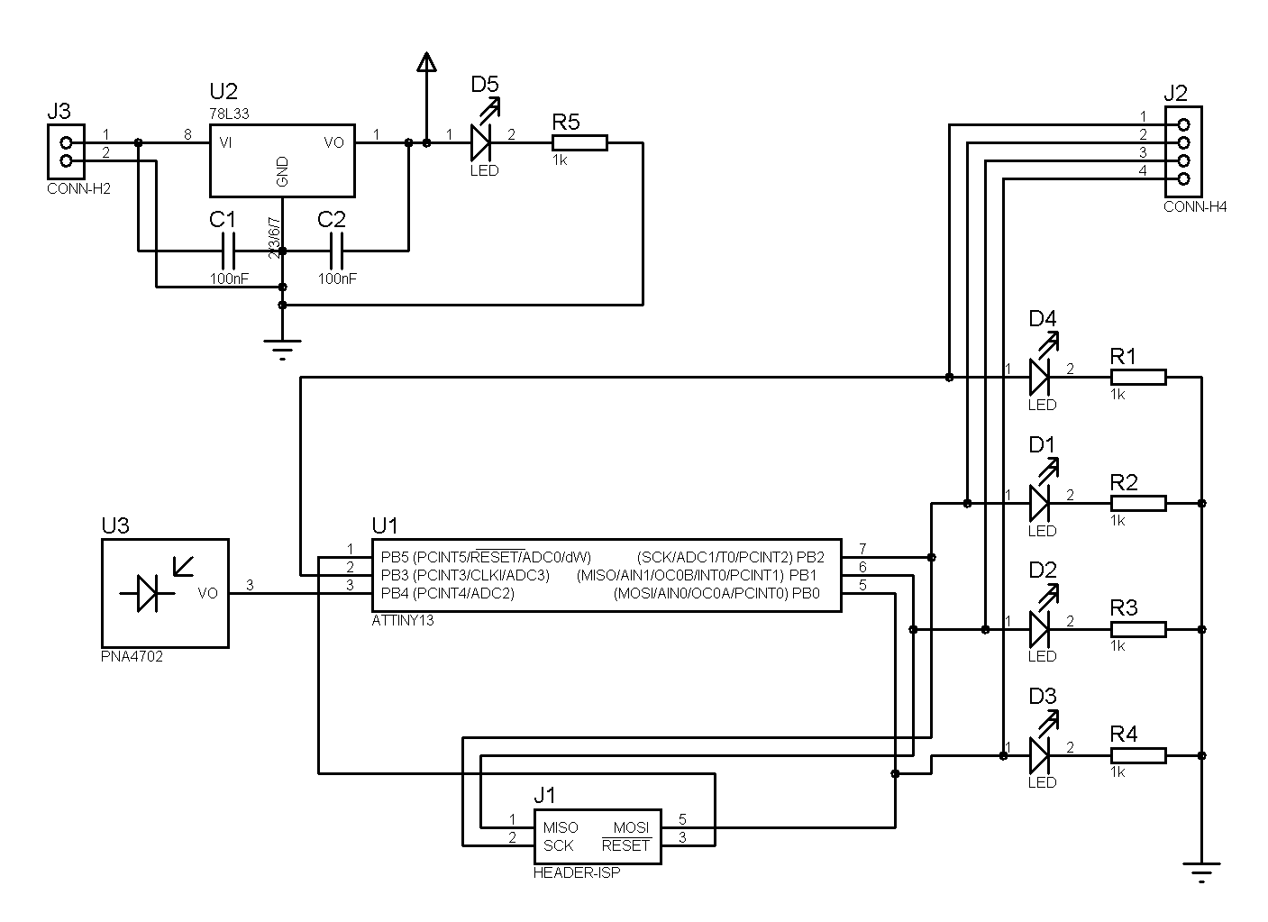
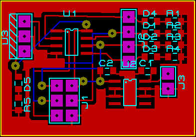
Building a reception circuit

The reception circuit is really quite simple. A small AVR Attiny13 was used. Four LEDs are connected to the tiny13's PORTB[0:3], which gives a four bit output and a way to visualize the output. (Especially useful during testing). The IR sensor, a Panasonic PNA4203 is also connected to the AVR. This IR-sensor is a standard 38 kHz infrared phototransistor with filtering and amplifying circuits onboard. Also attached to the circuit board is a 3.3V regulator.

Programming the reception circuit

While the reception circuit turned out pretty nice and ordered, the code it runs is a whole different story. The C-code posted here is merely for fun, you could say. If you are interrested in building or programming something like this yourself, I would recommend writing your own program, and not even try to understand mine. I barely do.

Schematic

PCB layout

Source Code
//--------------------------------------------------------------//
//			!!!ADVARSEL!!!	                        //
//								//
//                        LUFTSLOTTKODE			        //
//								//
//  - bør støpes inn med smeltelim og aldri tulles mer med!	//
//								//
//	Dewald de Bruyn - eksamensperioden høst 2007		//
//								//
//			!!!ADVARSEL!!!				//
//--------------------------------------------------------------//

#include <avr/io.h>
#include <avr/interrupt.h>
#define true 1
#define false 0
#define inputPin (PINB & (1<<PIN4))

#define MENUBUTTON 0x0F
#define PLAYBUTTON 0x09
#define LEFTBUTTON 0x01
#define RIGHTBUTTON 0x08
#define UPBUTTON 0x02
#define DOWNBUTTON 0x04
#define TIMEOUT 16

char interrupt_received;
unsigned int timerTicks;
int output = 0;
void receiveNrBits(const int);
int checkForPlayMenuRev(void);

ISR(PCINT0_vect){
	TCNT0 = 0x00;
	timerTicks = 0;
	interrupt_received = true;		//Set interrupt receive flag?
}
	
ISR(TIM0_OVF_vect){
	timerTicks++;
	if(timerTicks == TIMEOUT){
		timerTicks = 0;
		PORTB = 0x00;
	}
}


unsigned int startReceive(){
	if(inputPin != 0)return 0;
	while((TCNT0 < 0xFF) && inputPin == 0);
	if(TCNT0 != 0xFF)return 0;
	while(inputPin == 0);
	unsigned int tmp = TCNT0;
	TCNT0 = 0x00;
	if(((tmp>>4) < 0x05)||((tmp>>4) > 0x06))return 0;
	while(inputPin != 0);
	tmp = TCNT0;
	TCNT0 = 0x00;
	
	if((tmp>>4) < 0x0A){
		return 0;
	}
	
	receiveNrBits(33);
	
	while(inputPin != 0);
	tmp = TCNT0;
	TCNT0 = 0x00;
	
	if((tmp>>4) == 0x03){
		//Received Play, Menu or Rev
		for(int i = 0; i < 3; i++){
				receiveNrBits(1);
				if(checkForPlayMenuRev()){
					if(i == 0)return MENUBUTTON;
					if(i == 1)return PLAYBUTTON;
					if(i == 2)return LEFTBUTTON;
				}
			}
			return 0;
		}
		else{
			//Received plus, minus or fwd
			receiveNrBits(1);
			while(inputPin != 0);
			tmp = TCNT0;
			TCNT0 = 0x00;
			if((tmp>>4) != 0x03)return DOWNBUTTON;
			receiveNrBits(1);
			while(inputPin != 0);
			tmp = TCNT0;
			TCNT0 = 0x00;
			if((tmp>>4) == 0x03)return RIGHTBUTTON;
			if((tmp>>4) != 0x03)return UPBUTTON;
		}
		return 0;
	}
	
int checkForPlayMenuRev(){
	while(inputPin != 0);
	unsigned int tmp = TCNT0;
	TCNT0 = 0x00;
	if((tmp>>4) == 0x03){
		return true;
	}
	else return false;
}

void receiveNrBits(int nr){
	for(int i = 0; i < nr; i++){
		if(inputPin != 0){
			while(inputPin != 0);
		}
		else{
			while(inputPin == 0);
		}
		TCNT0 = 0x00;
	}
}


int main(){
	DDRB = 0x0F;
	GIMSK |= 1<<PCIE;
	PCMSK |= 1<<PCINT4;
	TCCR0B |= 1<<CS02;
	TIMSK0 |= 1<<TOIE0;
	sei();
	while(1){
		if(interrupt_received == true){
			GIMSK &= ~(1<<PCIE);			//Disable pin interrupts
			interrupt_received= false;		//Clear interrupt receive flag
			unsigned int result = startReceive();	//Start receiving sequence
			if(result > 0)output = result;
			PORTB = (output & 0x0F);
			GIMSK |= 1<<PCIE;			
		}
	}
}
  • No labels