...
The interrupter generates the signal which drives the resonant circuit (coil rig) at its resonant frequency f0. As long as the input signal X2 is high the output produces a square wave with fundamental frequency f0. It does this by means of a positive feedback loop. The feedback signal X8 is retrieved with a sensing transformer around the output wire from the power amplifier (section 2.4), before being clamped, rectified, and schmidt triggered. This results in a cleaned up normalized representation of X8, lets call this signal X80. The flanks of X80 represents when the output current passes zero (this is when we want to switch the polarity of the output X5). X80 is fed to the output via gates controlled by a latch. X5_B is inverted in relation to X5_A (for push-pull operation). This circuit is shown in fig. 2.5, U1A is the latch witch is central to the operation of the interrupter. It has Four inputs SD, CP, D, and RD, wich are ’Set Data’ (active low), ’Clock Pulse’, ’Data’, and ’Reset Data’ (active low) respectively. And two outputs; Q wich is the normal output, and Q inverted wich is the inverted of Q at all times, Q inverted is unused in this circuit.
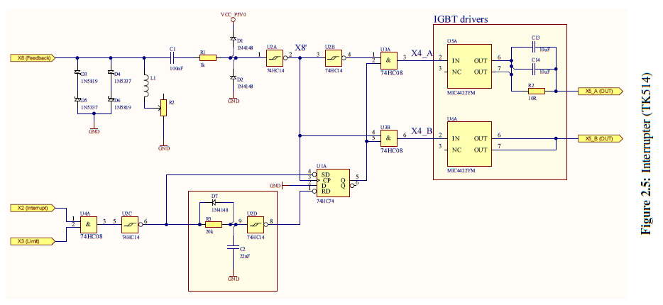
Initially no current is flowing in the resonant circuit therefore no voltage is present on X8, but because of C1 the the input of U2A is undefined. Let us look at the case of the output of U2A being high and the input X2 being low. Then the initial values of the signals are as shown in fig. 2.6, SD is high (inactive) CP is high, D is low, RD is low (active), Q is low, X4_A and X4_B is low.
...